
Measure amplifier output?


Thread Starter
50 Watt CAFz'r
Joined: Dec 2001
Posts: 197
If i try to measure the output of an amplifier with my voltmeter will it fry the meter? How do magazine reviewers do it? To find out the power it's V^2/Ohms right? Do i just need a really high quality voltmeter?
Guest
Posts: n/a
Measuring amp power is kind of futile for a system that plays music as the impedence of the woofer system will change constantly, and often dramatically, with frequency. If you want to know how much power it plays at freq. 'x' however...
The most practical way is to use two meters, a standard voltage meter set to AC volts and a clamp on ammeter. Power = Voltage * Current.
The most practical way is to use two meters, a standard voltage meter set to AC volts and a clamp on ammeter. Power = Voltage * Current.

1000 Watt CAFz'r
Joined: Oct 2003
Posts: 1,649
The following is quoted from the basic car audio electronics thinger..
EQUIPMENT NEEDED TO MEASURE OUTPUT POWER
To accurately measure output power, you will need:
1.A regulated D.C. power supply capable of powering any amplifier that you need to test
2.A set of high power resistors. They must be rated to handle the power output of any amplifier which you need to test.
3.An oscilloscope to view the waveform.
4.Some sort of tone generator. A sine wave generator is a good choice but you may be able to get by with a CD player and a test tone disc.
5.A digital voltmeter capable of measuring A.C. voltage. A true RMS meter would be nice.
NOTE:This information is only to let you know how the test is done. If you have all of this equipment, you will probably already know how to make this test.
TEST EQUIPMENT SETUP
Connect the 12v power supply to the power wires on the amplifier.
Connect the power resistors (dummy loads) to all of the channels of the amplifier.
Set the gain controls for all channels of the amplifier to the same level. Either all of the way up or all of the way down will probably be the easiest. You can make fine gain adjustments at a later time.
Connect the tone (sine wave) generator to all of the amplifier channels. Turn the output level of the tone generator all of the way down.
Turn the power supply on. If it is adjustable, set it where you want it (12 volts, 13.8, 14.4 your choice).
Power the remote terminal of the amplifier.
Measure the output voltage of the D.C. power supply (it should be the same as before the amplifier was turned on).
Set all equalization to the off position and set all crossovers to full range.
Set the output frequency of the generator to any frequency that you want. I generally use 100hz. You should always use the same frequency or at least make note of the frequency used during the test.
Slowly increase the output of the tone generator until the output of the amplifier is approximately 2 volts A.C. Now set all of the gains to match the output of all of the channels.
Connect the oscilloscope to any channel (they should all be the same since you tweaked them).
Monitor the output voltage of the power supply, either with your volt meter or by the digital meters on the power supply. If the power supply doesn't have digital meters, use a digital multimeter.
Slowly increase the output of the tone generator while watching the oscilloscope. Increase the level until the top and/or bottom of the sine wave flattens out. Reduce the level until the wave is 'clean' again.
Now see if the power supply voltage has held to the preset value. Reduce the output level of the generator. If the D.C. voltage changed during the test, you must take this into account. A well regulated supply will have held the preset voltage.
Now connect the A.C. voltmeter to the output terminals of one channel. The channel connected to the scope would be a good choice.
Again Increase the level of the generator until just before the amplifier starts to clip. Make note of the voltage reading.
Turn the power supply off.
Quickly disconnect the dummy load of one channel and measure its exact resistance while it is still hot. The value of the resistor will change slightly as it heats up.
Now use the Ohm's law formula, P=E^2/R. If we found that the amplifier drove 35 volts A.C. across the resistor and the resistor had a D.C. resistance of 4.08 ohms, the amplifier produced 300.25 watts RMS.
P=35^2/4.08
P=1225/4.08
P=300.25 watts RMS
NOTE:
1.If the D.C. power supply does not hold its preset voltage, the power output will be lower than the amplifier is capable.
2.This test cannot be done using speakers in place of the dummy loads. The speakers will give you a false high reading at most frequencies.
Guest
Posts: n/a
Yep, that more than covers it.. Or, you can bring me your amp and I'll test it for ya for a small fee.. Right now, I am charging a flat rate of $25.00 per amp (no taxes er nuthin' fer now), plus $20 for each additional amp, up to three. I am going to try and restrict this to amplifiers under 1500 Watts rated output power untill I can run another power circuit down to the basement with some 10/3.
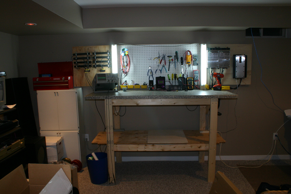
I have all the goodies needed to test pretty much any mobile audio amp and almost any impedance from 0.5 ohms at 2,000W up to 4 ohms or higher. I have two of my three power supplies set up on my new bench. I also have a good quality scope, distortion meter, signal generator, two true RMS meters, a true RMS current clamp, and another voltmeter for watching supply voltage to test efficiency.
I must have more stuff down here, but that's all that applies to amp testing that I can think of.
I rebuilt my bench on the weekend, here's a pic if you guys are interested..

50 Watt CAFz'r
Joined: Nov 2003
Posts: 278
[img]graemlins/headbang.gif[/img] [img]graemlins/headbang.gif[/img]
http://www.concept-intl.net/download/measurwatts.pdf
[ November 17, 2003, 10:22 PM: Message edited by: ChevySQ ]
http://www.concept-intl.net/download/measurwatts.pdf
[ November 17, 2003, 10:22 PM: Message edited by: ChevySQ ]

Hey pipes you're alive, how about you refund me that money that I gave you for that amp that doesn't work? 
You've obviously haven't replied to my messages, and since you're going to look at this topic you're going to see this.
You've obviously haven't replied to my messages, and since you're going to look at this topic you're going to see this.
Guest
Posts: n/a
I saw that concept thing a few years ago... Non-True RMS voltmeters use a 'fudge factor' to calculate RMS power, but it only works at 60Hz. This test will improve if you use that frequency.
As for this test compared to mine. Mine more closely mimics what all the published specs are. When you use a speaker, you can't guaratee what load the amp is seeing, or if it is going to change as you apply power.
But whatever works for you guys...
As for this test compared to mine. Mine more closely mimics what all the published specs are. When you use a speaker, you can't guaratee what load the amp is seeing, or if it is going to change as you apply power.
But whatever works for you guys...
Thread Starter
50 Watt CAFz'r
Joined: Dec 2001
Posts: 197
Thanks for the replies. I would just bring my amps somewhere, but i want to see what they do with my own equipment. For example my head unit might only have a 2 volt preout instead of 6 or 8v and my charging system only 13.5 instead of 14. I dont think it's futile, it would be useful to see what it is now, and what it measures after i add a line driver or switch head units etc. I dont want to measure the amp running at 16volts with 8volts input just so i can put a big sticker on my back window saying my amp makes 9527w. If my amp made that much power, id put the sticker on my front window instead 
p.s. ignore the whining guy. i have 2 witnesses that saw the amp working, powering 2 JLW6's, just fine not 15 mins before. they watched me unhook everything because i sold them the subs, and i brought the amp directly to that guy. [img]graemlins/dunno.gif[/img]
p.s. ignore the whining guy. i have 2 witnesses that saw the amp working, powering 2 JLW6's, just fine not 15 mins before. they watched me unhook everything because i sold them the subs, and i brought the amp directly to that guy. [img]graemlins/dunno.gif[/img]
The whining guy?
I have more witnesses to show the ****ing amp doesn't work. Tried hoooking it up at 4 ohm, 1 ohm, one coil at 2 ohm, NOTHING. Hooked up TWO different kenwoods amps right after and everything worked fine.
You haven't replied to my messages. So you basically sold me a $250 paper wight and you wonder why I'm mad?
If it works fine then take it back and give me my money.
[ November 18, 2003, 03:43 PM: Message edited by: JohnnyToronto ]


